
Learning about Ohm’s Law
I saw a post that basically said I was useless unless I understood Ohm’s Law, so here I am trying to learn Ohm’s Law!

An electrician (not me... yet!)
Published August 4, 2026
In my post about wiring up an electrical circuit, I wanted to learn more about how to read the label printed on the cable I was using. It read the following:
14AWG 2CDR NMD90
I understood almost everything:
- 14AWG means that it’s using the American Wire Gauge system for measuring the diameter of wires, and in this case, the wire is 14-gauge
- NMD90 is a common way in Canada to refer to non-metallic sheathed cable for use in wiring indoors in dry locations at a maximum temperature of 90°C
- N: Non-metallic
- M: Moisture-resistant outer jacket
- D: Dry location use
- 90: 90°C temperature
And then I didn’t know what 2CDR meant yet so I looked it up and came across a blog post that basically said if I didn’t know what $\text{V=IR}$ then I’m not going to understand the post about Current Divider Rule, since that’s what CDR means (right?? – spoiler alert: no), so I figured it’s time to learn all about Ohm’s Law so I can understand those 3 letters printed on the wire!

A wire with printed text: “14AWG 2CDR NMD90 NYLON CABLE”
What is Ohm’s Law
According to Wikipedia:
Ohm’s law states that in a well-behaved conductor (a so-called ohmic conductor), the electric current between two points is directly proportional to the voltage (the difference of electric potential) across the two points. Introducing the constant of proportionality, the resistance, one arrives at the following mathematical equation used to describe this relationship:
$$\text{V = IR}$$
or, equivalently, at the same equation expressed in terms of the reciprocal constant of proportionality, the electrical conductance,
$$\text{I = GV}$$
Wikipedia
And slightly below that here, it also shows that Ohm’s Law can be represented in 3 ways for circuits:
$$I={\frac {V}{R}}\quad {\text{or}}\quad V=IR\quad {\text{or}}\quad R={\frac {V}{I}}$$
To understand the above, we need to first understand what each letter means:
- I: the current through the conductor, in amperes “A”
- V: the voltage measured across the conductor, in volts “V”
- R: the resistance of the conductor, in ohms “Ω”
- this can be typed on macOS by pressing Option+Z, which is kinda fun because Z is the symbol to talk about resistance with impedances, e.g. $\text{V = ZI}$
I found this resource from Iowa State University quite helpful with its interactive diagrams. You can really go quite deep here into circuits!
Circuits: Series circuits and Parallel circuits
An electrical circuit is a closed path that allows electrical current to flow and pass energy. According to All About Circuits:
In a series circuit, all components are connected end-to-end, forming a single path for current flow.
In a parallel circuit, all components are connected across each other, forming two sets of electrically common points.
A branch in a parallel circuit is a path for electric current formed by one of the load components (such as a resistor).
All About Circuits
Here are some diagrams.
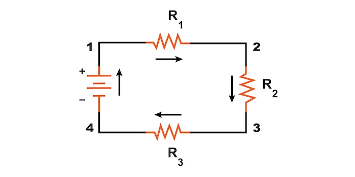
A series circuit with 4 resistors
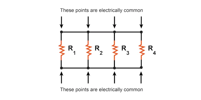
A parallel circuit with 4 resistors
A series circuit runs in a continuous line, while a parallel circuit has branches and points that connect them.
Using Ohm’s Law, we can calculate the current for each branch based on the changing variable of the resistance.
What is the Current Divider Rule
In order to understand the Current Divider Rule, we need to be able to work with all the above-mentioned variables:
- the current in amperes is “I“
- the resistance in ohms (Ω) is “R“
- the voltage in volts is “V“
The above-mentioned fractions can be arranged in any way to calculate Voltage, Current, and Resistance.
To calculate voltage (V), you do:
$$\textbf{V}=IR$$
To calculate current (I), you do:
$$\textbf{I}={\frac {V}{R}}$$
To calculate resistance (R), you do:
$$\textbf{R}={\frac {V}{I}}$$
The Current Divider Rule applies to parallel circuits.
An example of a parallel circuit
Let’s try to understand this using an example of a parallel circuit. Given the following variables:
- V = 6
- R1 = 1 kΩ
- R2 = 3 kΩ
- R3 = 2 kΩ
We can fill out a table as so:
| R1 | R2 | R3 | Total | ||
|---|---|---|---|---|---|
| E | 6 | 6 | 6 | 6 | Volts |
| I | Amps | ||||
| R | 1 kΩ | 3 kΩ | 2 kΩ | Ohms |
So to calculate I we need to use the above-mentioned formula $\textbf{I}={\frac {V}{R}}$
- $\textbf{$I_{R1}$}={\frac {6}{1k}}=0.006=6mA$
- $\textbf{$I_{R2}$}={\frac {6}{3k}}=0.002=2mA$
- $\textbf{$I_{R3}$}={\frac {6}{2k}}=0.003=3mA$
That means we can fill out those values in the table as so, and then add them up to find the total:
| R1 | R2 | R3 | Total | ||
|---|---|---|---|---|---|
| E | 6 | 6 | 6 | 6 | Volts |
| I | 6mA | 2mA | 3mA | 11mA | Amps |
| R | 1 kΩ | 3 kΩ | 2 kΩ | Ohms |
Now to calculate the total resistance, we need to switch formulas to use the one that’s $\textbf{R}={\frac {V}{I}}$, so:
$$\textbf{R}={\frac {6}{11m}}=545.45$$
We can update the table with the final value:
| R1 | R2 | R3 | Total | ||
|---|---|---|---|---|---|
| E | 6 | 6 | 6 | 6 | Volts |
| I | 6mA | 2mA | 3mA | 11mA | Amps |
| R | 1 kΩ | 3 kΩ | 2 kΩ | 545.45 Ω | Ohms |
The Current Divider formula is as follows:
$$I_{n} = I_{total} \frac{R_{total}}{R_{n}}$$
In English, we could say that for the Current Divider Formula, the current of the branch is equal to the total current multiplied by the total resistance divided by the branch’s resistance. I think. 😅 This is Day 1 circuits using the internet without any formal education, so if this is wrong, please let me know.
Now, the Current Divider Formula can be used for the above examples:
$$I_{R1} = 11 mA \frac{545.45Ω}{1 kΩ} = 6 mA$$
$$I_{R2} = 11 mA \frac{545.45Ω}{3 kΩ} = 2 mA$$
$$I_{R3} = 11 mA \frac{545.45Ω}{2 kΩ} = 3 mA$$
I must thank All About Circuits for this resource.
Now, to go back to our current question, how does this relate to what’s written on the wire? (2CDR) – It turns out, it doesn’t! 2 CDR, when printed on wire, actually refers to that there are 2 conductor wires in the cable (a white wire and a black wire). So when I google “CDR electrical” and “Current Divider Formula” is my first hit, it’s technically not wrong, since Current Divider Formula is related to electrical, they just happen to also use “CDR” printed on the NM cable to denote the number of conductors!
So was all that learning a waste? Absolutely not! While learning about Ohm’s Law and the Current Divider Formula, I got to learn that it’s not actually what is referred to on the NM cable.
So to review our understandings of what’s printed on the wire:
- 14AWG means that it’s using the American Wire Gauge system for measuring the diameter of wires, and in this case, the wire is 14-gauge
- NMD90 is a common way in Canada to refer to non-metallic sheathed cable for use in wiring indoors in dry locations at a maximum temperature of 90°C
- N: Non-metallic
- M: Moisture-resistant outer jacket
- D: Dry location use
- 90: 90°C temperature
- 2CDR is the number of conductors in the cable, in our case 2, because there’s a white wire and a black wire, and the ground wire is not counted as a conductor
So while that was a round-about way of getting to our conclusion, we learned something new in the process.