
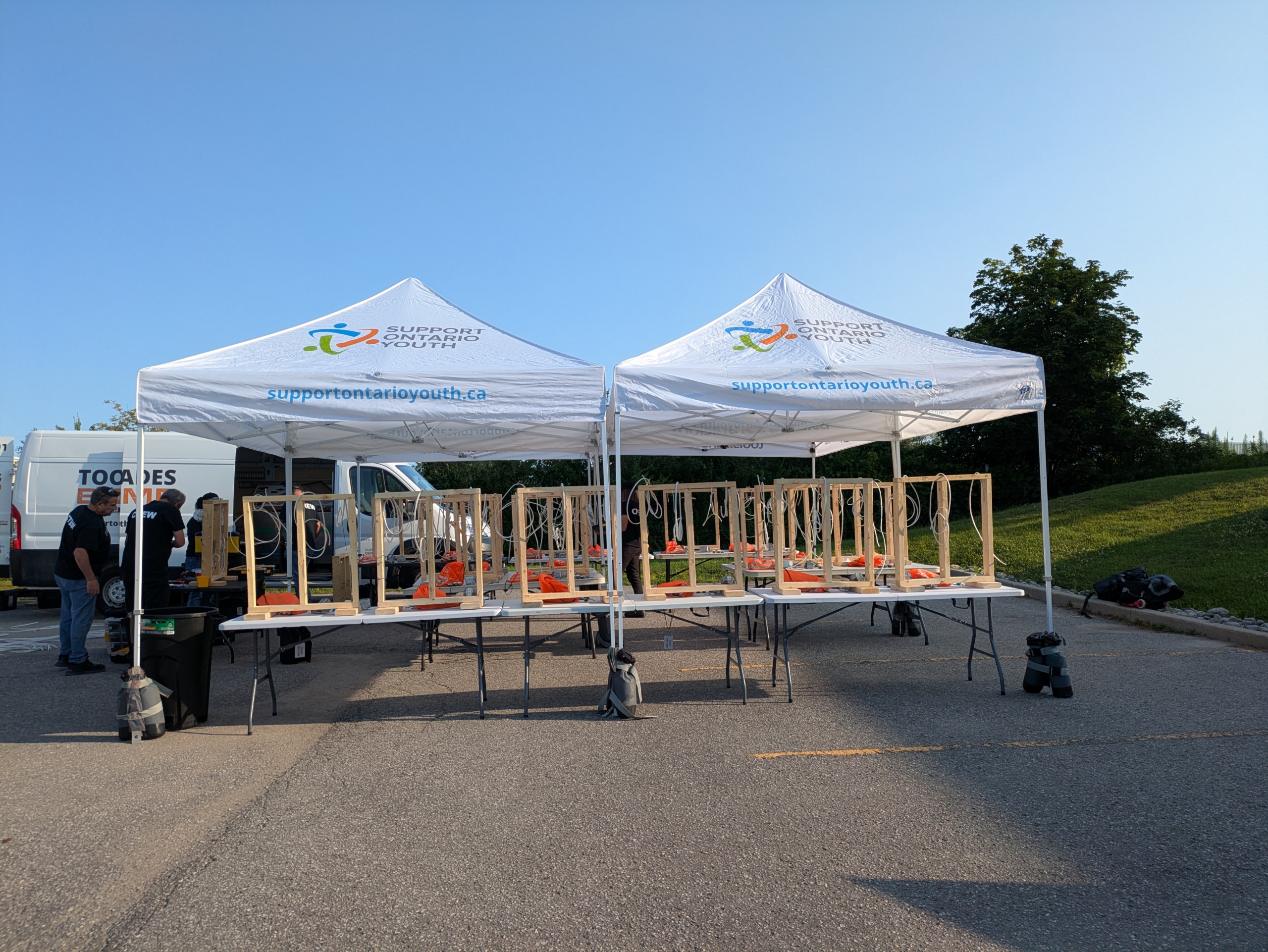
On a bright sunny morning, I rolled up to IDEAL Electrical so that I can do some hands-on electrical and plumbing tasks at the Tools in the Trades Bootcamp by Supporting Ontario Youth.
It was a beautiful day with clear blue skies. I arrived a bit early so I had enough time to find parking, put on my safety boots, and check-in, leaving some extra time to chat. When I approached I saw some tents set up with the electrical and plumbing activities planned for the day.
This workshop simulated a new build, which means there was no drywall or wall-finishing material at all, just the studs.
If you are attending this workshop and you found this post from Google, I will give you fair warning that this post will contain details that may be considered spoilers for your experience. In order to have the full experience, if you are going to this workshop, I would recommend closing this tab and revisiting after so that you can experience everything on your own. I wouldn’t want to spoil your experience.
The boxes
There is a variety of boxes available on the market, and the ones you choose depend on your project. In our case, we were using galvanized steel boxes designed to be installed indoors in wood studs. We worked with 3 different types of boxes:
- 2-gang device box, designed to fit 2 devices, in our case 2 light switches
- 1-gang device box, designed to fit 1 device, in our case, 1 receptacle
- Octagonal box, designed for light fixture installations, for example in ceilings (though ours was against a wall)
The brand of boxes we used were Iberville.
These boxes included mounting features to assist with mounting the boxes:
- Positioning tabs, aligned to the frame for a quick install compatible with $\frac{1}{2}$” drywall
- Metal “teeth” that are designed to be hammered into so that the box can grip onto the stud and be held in place while you are securing it with screws
These boxes also included wiring-specific features:
- Pre-mounted clamps, to make it easy to insert and secure non-metallic sheathed cable to the box
- Pre-mounted screws for ground screws to make it easy to slip the grounding wire in and simply tighten, instead of having to dig into your screw organizer to find ground screws
- Knockouts that are easily removed when needed
There are other brands and types of boxes, including boxes made of an electrical-safe plastic instead of steel, but since we didn’t use those, I won’t be going into that in this post.
Mounting the boxes
To mount the boxes, we must perform the following steps:
- Follow the instructions to ensure you are going to mount the boxes at the correct height, measuring from the ground up (or from the ceiling down, if your instructions provide those instead). This will ensure that the box is mounted in the correct spot. Be sure to note which end of the box is relative to the measurement, e.g. the bottom of the box to the floor.
- Follow the instructions to ensure you are going to mount the boxes at the correct depth. In our case, our boxes have positioning tabs on them that allow us to mount the tabs flush with the studs, and it automatically provides the required half inch clearance required for drywall
- The teeth will be sitting on top of the wood studs. Once the correct position is found, you can hammer onto the box to ensure the teeth bite into the studs
- Secure the box to the studs using screws. In our case, we were provided with red Robertson screwdrivers and screws for the external installation (and green Robertson for the internal parts). At this moment, I wish I had brought my power drill with me to speed things up!
Once all 3 boxes are secured to the frame, it’s time to move on to feeding the wire in.
The wire
The wire we are working with 14/2 AWG NMD90, which is non-metallic sheathed cable that has 2 wires in it (1 black, hot, and 1 white, neutral, and 1 ground, which is not counted in the wire count). The exact printing on the wire reads:
14AWG 2CDR NMD90
To understand what all that means, we need to have an understanding about how electrical circuits work. That’s diving fairly deep into the theory at this point so it won’t be addressed here, but I promise to do a post on this in the future.
For now, what we need to know is that this 14-gauge wire will be what we’re going to be using to wire our 14-amp circuit with 2 light switches, a receptacle, and a light fixture.
Before the wire is pulled, we need to remove the sheathing. You can do this in the box too but it’s easier to remove the jacket if you do it beforehand. For this task, we were provided with a wire stripper designed to strip the jacket of NM cable cleanly and quickly.
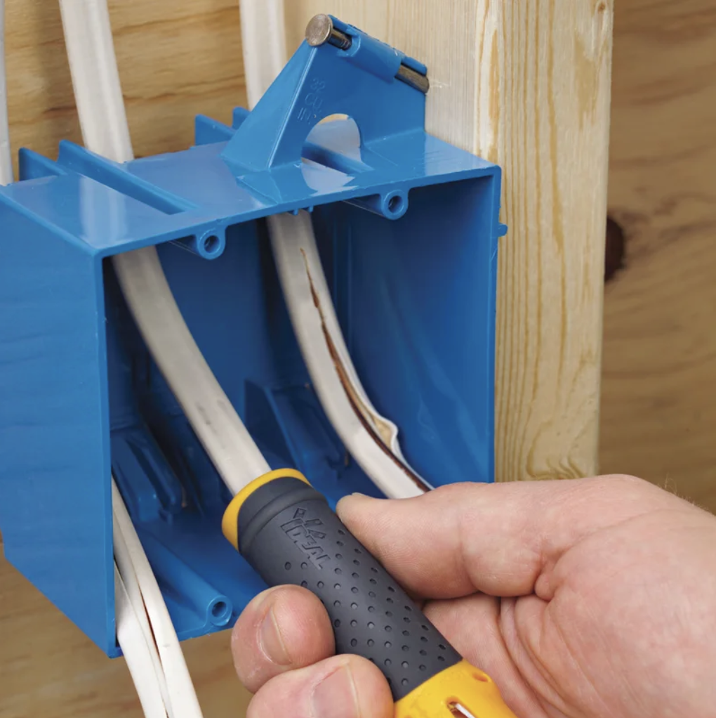
IDEAL Electrical Lil’ Ripper Stripper
To use the jacket stripper, named Lil’ Ripper Stripper, we did the following:
- Insert the wire into the end with the sharp pin and pushed it through, ensuring friction so that you can feel the sheathing being cut
- Remove the wire device and grab the provided side-cutters for cutting the wire.
It looks like this device can also cut the jacket off, especially since the other end has a blade in it, but we weren’t taught how to do that with the device and to just use the side-cutter pliers.
Pulling the wire
In order to know where/how to pull wire, we need to understand where the power source is coming from. In our case, it’s coming from the top (i.e. the make-shift ceiling). In our case, a battery with alligator clips will feed our project.
There were 3 wires ready for us:
- The shortest wire: A wire that goes from the power source in the “ceiling” to the 2-gang box
- The middle-length wire: A wire that goes from the 2-gang box to the receptacle on the next stud
- The longest wire: A wire that goes from the 2-gang box to the light fixture on the stud next to the receptacle box, so 2 studs down from the 2-gang box
The wire lengths are most likely not representative in any way of a real installation, and the studs are significantly smaller and closer than a real wall.
Once the wire is pulled, it’s important for it to have the non-metallic sheath stripped from it.
After pulling the wires as described above, the 2-gang box should look something like the image below.
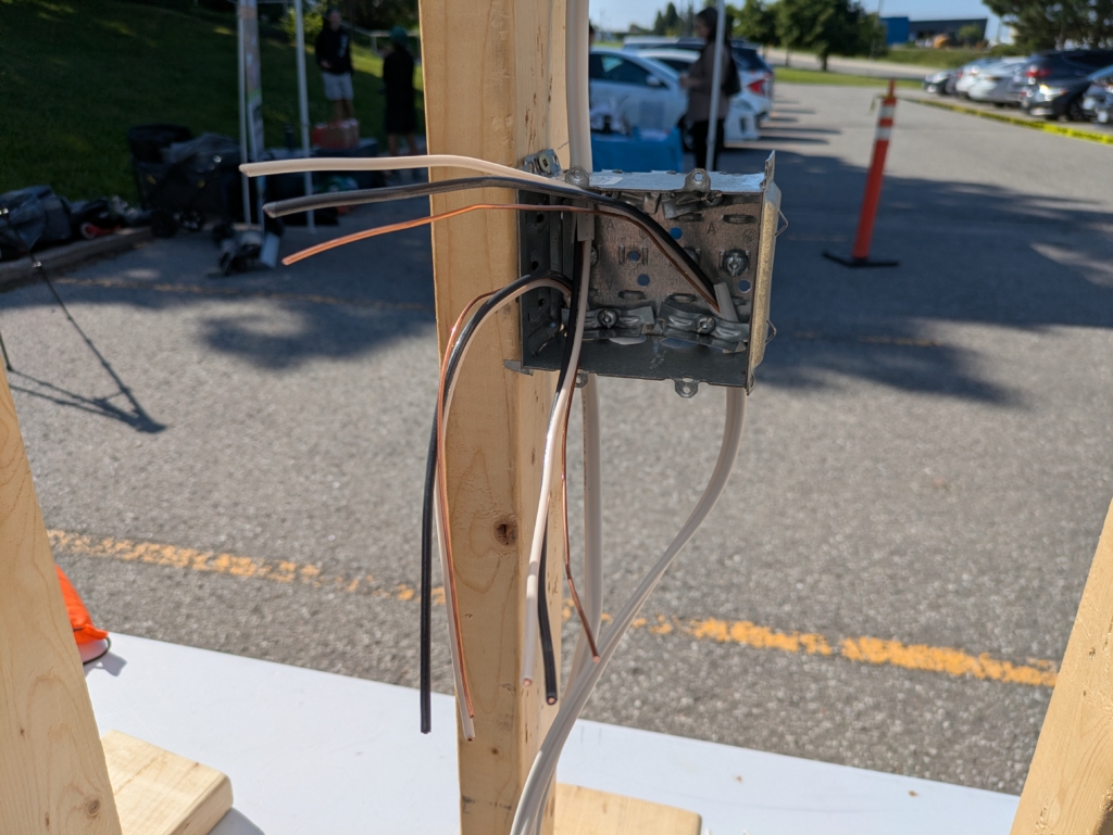
2-gang electrical box with wire fed from the power source above, and out of 2 knockouts below, to the receptacle and to the light fixture
The next step is to feed the wire through the knockouts we’re going to use. Since these boxes are reused, the knockouts were already removed for us, but in the case of new boxes, you’ll need to remove only the knockouts you’re going to use. In the case of the 2-gang switch, it was 1 from the top and 2 from the bottom.
For safety reasons, it’s important that knockouts only be removed if they are going to be used. This is to prevent debris, fingers, animals, insects, etc. from entering the boxes, which would risk them coming into contact with conductors and causing arcing. So for safety reasons, it’s important to only remove knockouts that are going to be used. If you find yourself with a box you’re reusing that has open knockouts, you should buy knockout covers, which are caps designed to fit knockouts. Make sure to buy the ones compatible with your box material and knockout size.
The boxes have clamps and pre-installed screws. We just need to tuck the sheathed part of the cable underneath the clamp and screw it down. We don’t want to screw it too tightly but we also don’t want it too loose where it can fall out of the bottom knockouts or get easily pulled out of the top knockout. These should ideally be screwed in by hand. If over-tightened, there’s a risk that the insulation around the conducting wires could break and the conductors can come into contact with the box. Over-tightening can cause short circuits as described in these discussion posts here and here.
Now that we know how to feed the NM cable through the knockouts and secure them into the box, we need to do the same for the other 2 device boxes.
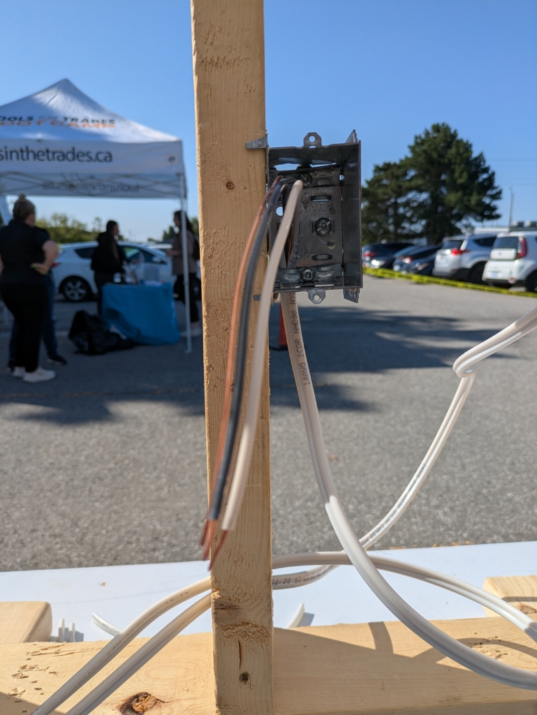
1-gang device box with NM cable pulled through the bottom knockout
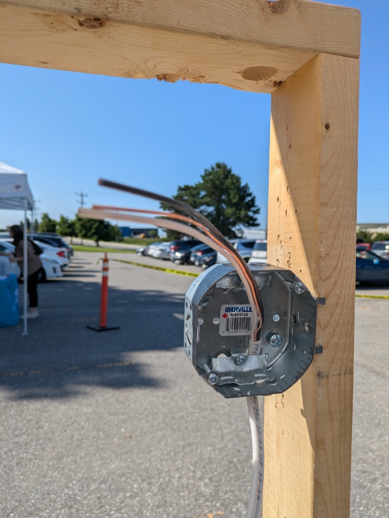
Octagonal box with NM cable pulled through one of the bottom knockouts
Stripping the wire
We already stripped the jacket off the cable but now we have to strip the insulation off of the conductors, which are the white and black wires.
For this task, we were provided with the IDEAL T-Stripper wire strippers, designed for stripping insulation off of 18-10 gauge solid and 20-12 gauge stranded wires.
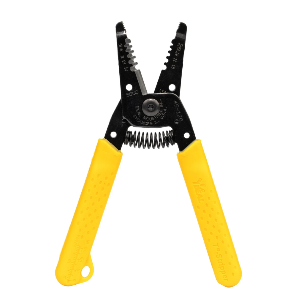
IDEAL Electrical T-stripper
We are using solid 14-gauge wire so we’ll use the side that reads “solid” and the groove that reads “14.”
The amount of insulation we cut off must be exact:
- Too much insulation cut off will leave exposed conductors, which can cause arcing or short circuits
- Too little insulation cut off could cause the insulation to interfere with the conductive parts of the terminal screws, resulting in not enough wire making contact with conductive surfaces due to excessive insulation
We need to strip off enough that we can wrap it around the terminal screw and screw it down, with as little remaining copper visible as possible.
I found initially I was cutting off too much insulation, so I’d trim down the wire with the side cutters to make sure less conductor was exposed. You get the hang of it after a while. The recommended measurements are in the instructions.
Wiring the device
Next, we need to wire up the device, which will require bending the exposed copper to create a C or U shape so that it can wrap around the terminal screws of the devices. For this, you can use either the built-in holes of the wire strippers, or pliers. The tip of the T-stripper has grip and can be used for this purpose, or if you prefer dedicated needle-nose pliers, you can use those too.
Then, wrap it around the terminal screw so the edge goes in a clockwise direction. This is because we turn a screw clockwise to tighten it, we want to pull the conductor around the screw rather than push it away from the screw.
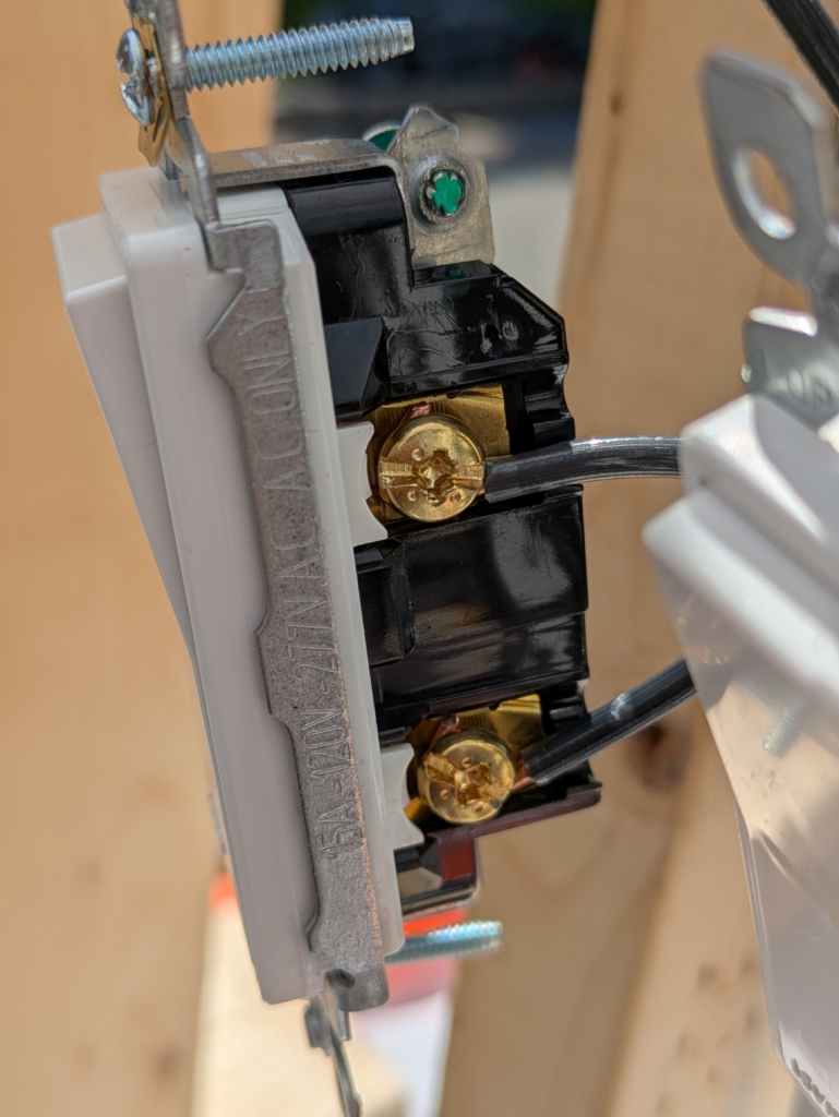
Light switch with black wires on the brass screws
The instructions didn’t specify to ground the devices but I over-heard a conversation with one of the electricians and she had said if the device provides a ground screw that it should be used, so I went ahead after hearing that and grounded the light switches since they did provide ground screws.
We do the same with the receptacles.
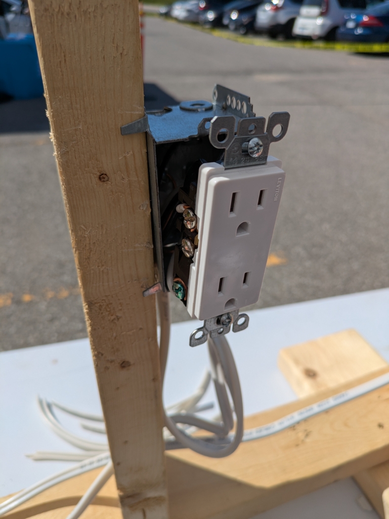
Receptacle with neutral, hot and ground connected
And lastly, we do the same with the octagonal box.
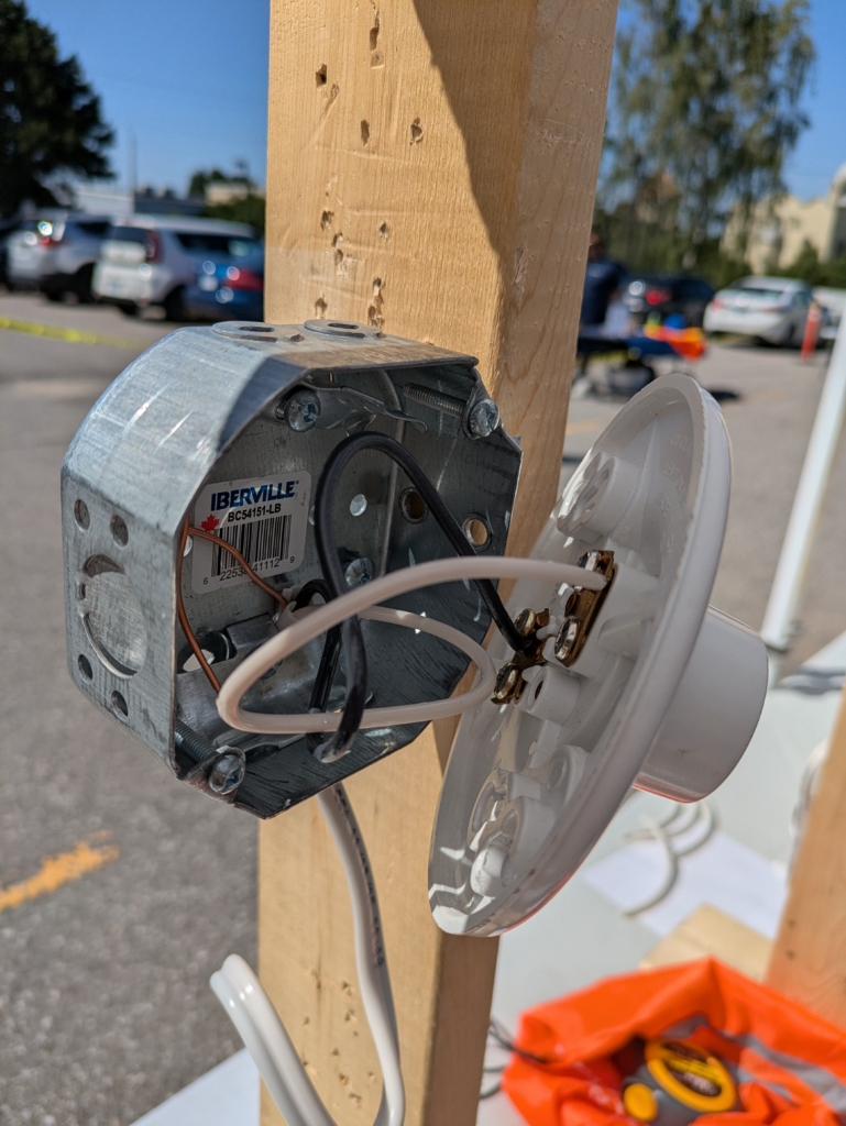
Octagonal box with light fixture and neutral, hot and ground wires connected
Pigtails
In our 2-gang box, we will need to create pigtails to split the power from the single source to 3 separate installations. For this installation, we needed to use wire nuts to connect the following:
- 2 x hot wire connection, each with a pigtail
- 1 x neutral wires connection
Our light switches do not require neutrals so we will not be creating a pigtail for the neutrals. They will join each other under the wire nut to provide the return path but they will not be fed to the light switches in the 2-gang box.
Below is a picture of the pigtails with the 2 devices wired.
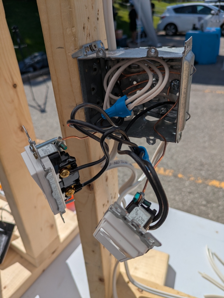
Two light switches connected to the power source using pigtails
I would’ve drawn out the circuits but I realize in my attempts I have a lot of learning to do up front before I’m able to draw wiring schematics, so I’ll save that for another post!
This is what it looks like with everything connected.
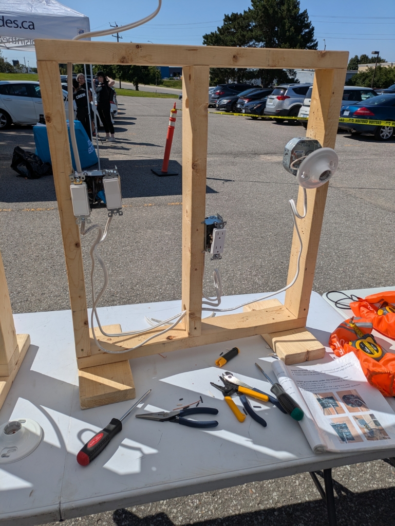
Completed electrical project
In the above image we can see the following:
- Power fed in from the top and into the top knockout of the 2-gang box
- 2 light switches in the 2-gang box
- 1 NM cable exiting the bottom left knockout that is fed to the receptacle
- 1 NM cable exiting the bottom right knockout that is fed to the light fixture
- A pigtail is created in the 2-gang box for the black wire and it includes 2 extra black wire pieces to ensure that we can connect both the light switches to the power source. This splits the incoming power source into 2, allowing us to divert this power to each of the 2 light switches.
- Each of the switched devices (i.e. the receptacle and octagonal box with light fixture) will be powered using the NM cables exiting the bottom of the knockouts, to the other screw of the switch.
- The ground wire from the power source—in our case bare copper but sometimes green—is secured to the steel box using the provided ground screw.
- Each of the NM cables passed through the bottom of the knockouts in the 2-gang box will:
- have their ground wires attached to the ground screws of each of the receptacles
- have their neutrals tied together in the wire nut
- have their hot wires fed to the bottom screw of their designated light switch
- The NM cable for the receptacle enters the bottom of its box and has:
- its copper wire attached to the ground screw on the receptacle
- its black wire attached to the brass screw on the receptacle
- its neutral wire attached to the silver (or white) screw on the receptacle
- The NM cable for the octagonal box enters the bottom of its box and has:
- its copper wire attached to the ground screw on the octagonal box
- its black wire attached to the brass screw on the light fixture
- its neutral wire attached to the silver (or white) screw on the light fixture
I’d draw a diagram if I knew how but for now I do not, so you’ll have to settle for text until I learn how to draw wiring schematics!
Below is a video showing some close ups of each part of the project.
Below is a video to show you it worked!
This was a very fun project and I highly recommend checking out one of the Tools in the Trades Bootcamps if you’re trying to get into the trades.
Oh, before we go, let’s not forget to clean up after ourselves so the next group can have a similarly awesome experience.
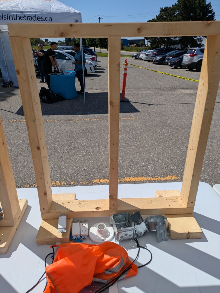
Project torn down and work area cleaned up